Introduction
With the new version of the TIA-222 code, many update have been done and some of them affects also how antenna effective projected area (EPA) areas are calculated. Now we can take into account smooth edges of the antennas which in return will reduce our EPA. Below you can see three different shapes and how they affect their EPAs.
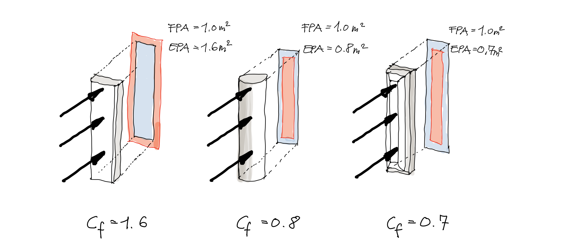
All three antennas have the same flat plate area (FPA) as $1.0m^2$. However, their force coefficient, $C_f$ (or drag factor) are very different due to their shapes.[1] In the first case the antenna has a flat area exposed to the wind with fairly sharp edges. It's $C_f$ value can be around $1.6$. In the middle, antenna has a round shape exposed to wind which gives a significantly lower $C_f$ value, about $0.8$. In the last case there is a "wind-friendly" panel antenna with nice and smooth edges. It yields to $C_f = 0.7$. The then by calculating the EPA of the antennas multiplying the $FPA $ with their respective $C_f$ values, the results will be proportionally the same. So from here we can see that how the antenna shape is a significant factor to establishing wind loads on them. We'll discuss the wind loads in a second.
While we are having values in the range of 0.7 - 1.6 for antennas, in the car industry it is not very difficult to find drag factors of cars under 0.3. In fact, the new Porsche Carrera 911 (992 model) has a drag coefficient of 0.29.
But back to our antennas, how the drag factor actually impacts the wind load on the antennas? We can look at different design codes, but the basic principal to compute force coefficient for a particular antenna (or other objects too) is the following. The drag coefficient is a key component in calculating wind load on an antenna. Its value varies for each antenna shape and must be determined experimentally or with the aid of Computational Fluid Dynamic (CFD) analysis. If the drag force on an antenna is known, the antenna's drag coefficient can be calculated using the following equation:
$$ C_f = \frac{f_w}{\frac{1}{2} \cdot \rho \cdot V^2 \cdot A} $$
where,
$ f_w = $ force on the object due to wind $(\frac{N}{m^2})$
$ \rho = $ the air density $(\frac{kg}{m^3})$
$ V = $ wind velocity $(\frac{m}{s})$
$ A = $ Cross Sectional Area Normal to wind direction (length x width), $(m^2)$
We are not going into more details about how to establish wind loads on antennas, but you can learn more about it in one of our other post How to calculate wind load on antennas as per Eurocode? But what if we have no available data about the antenna wind force from a wind tunnel or CFD analysis? TIA-222-H is helping us to determine the force coefficients. Table 2-9 in the code describes how to calculate them.
Sample calculation acc. to TIA-222-H
Let's assume that our panel antennas has dimensions as 2750x350x150 (HxWxL). We also know that the antenna has a smooth edges and the radius of this chamfer is 40mm.
Ratio of outside corner radius to width
The ratio of outside corner radius to outside width normal to the wind direction is a division. We need to divide the radius by the width normal to the wind. See below.
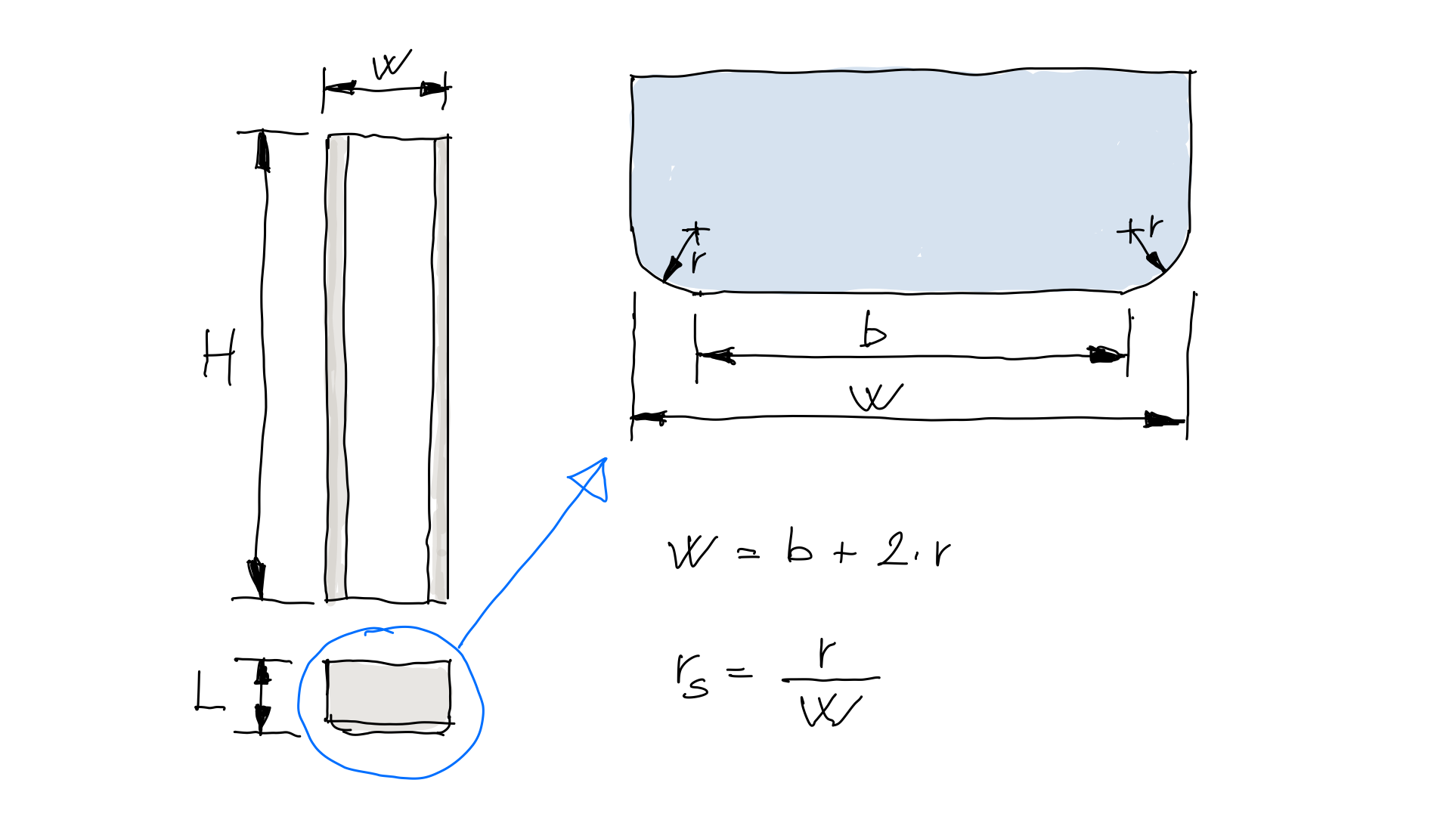
So, $r_s$ can be calculated as $r_s = \frac{r}{W}$. I used $r$ to specify the radius of the rounded chamfer. You may notice that as $r$, the radius grows, so the ratio too, and vice-versa. The more rounded is the antenna, the less wind drag it produces.
Now, we have all inputs we need to calculate the force coefficient, $C_a$:
$ H = 2.750m $
$ W = 0.350m $
$ r = 0.040m $
From here the ratio of outside corner radius, $r_s$:
$$ r_s = \frac{0.040m}{0.350m} = 0.114 $$
Aspect ratio
Next step is to find out the aspect ratio of the antenna. This can be computed simply as $\frac{H}{W}$ in frontal direction of the wind to the antenna:
$$ R_a = \frac{H}{W} = \frac{2.750m}{0.350m} = 7.86 $$
$C_a$ from table 2-9.
We know that if the aspect ratio is equals to 7.0 then:
$$ C_a = 1.4 - 4 \cdot (r_s) \geq 0.9$$
, or if the aspect ratio is $\geq 25.0$, then:
$$ C_a = 2.0 - 6 \cdot (r_s) \geq 1.25$$
In our case $R_a = 7.86$, so we cannot use these $C_a$ values directly. We need to interpolate to get our $C_a$ value. But first let's calculate the force coefficients if they would be exactly with the aspect ratios given byt the code.
$$ C_{a,7} = 1.4 - 4 \cdot (0.114) = 0.944 $$
and,
$$ C_{a,25} = 2.0 - 6 \cdot (0.114) = 1.316 $$
We have to also make sure that the calculated $C_{a,i}$ values are not greater than specified in the formula in Table 2-9. In our case we are fine, but with slightly bigger radius at the rounded edge will produce small $C_a$ values, thus the minimum limits will apply. Without any calculation, we can assume $C_a$ in the nearby of 0.944, so the interpolation should give a close figure to that. With a good assumption, we can verify our result if it makes sense, or not.
From here, $C_a$ can be calculated as:
$$ C_a = \left( \frac{1.316-0.944}{25.0-7.0} \right) \cdot (7.86-7.0)+0.944 = 0.962 $$
And as expected, it is close to the value of 0.944. It still not close to a Carrera 911 but we should appreciate this value as its already smaller than 1.0. Meaning that our EPA area is smaller eventually than the FPA.
For the curious, in case we wouldn't have any smooth edge on the antenna, then our $C_a$ value would yield to $1.43$, thus would be a significant increase on the drag area.
EPA area
From here it is a simple step to calculate the EPA area of the antenna. TIA code suggest the following formula for computing the total EPA of the appurtenances.
$$(EPA)_A = K_a[(EPA)_N \cdot cos^2(\theta)+(EPA)_T \cdot sin^2(\theta)]$$
where $\theta$ is the relative angle between the azimuth associated with
the normal face of the appurtenance and the wind direction. In our case we assume that the antenna is facing normal to the wind, so $\theta = 0^\circ$. By this the formula will be simplified as $\cos(0)^2 = 1.0$ and $\sin(0)^2 = 0$. We also ignore any shielding in this case, so $K_a = 1.0$.Then,
$$ EPA_A = K_a \cdot EPA_n $$
where,
$$ EPA_N = FPA_N \cdot C_a = 2.75m \cdot 0.35m \cdot 0.962 = 0.926m^2 $$
so,
$$ EPA_A = 1.0 \cdot 0.962 = 0.962m^2 $$
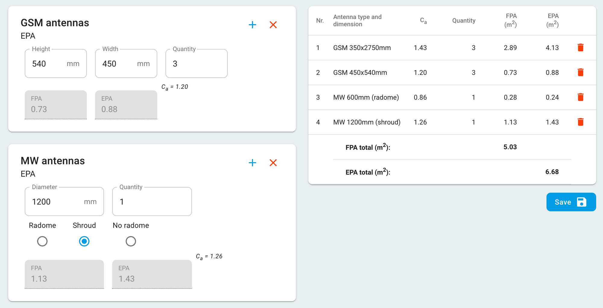
Conclusion
We have done an EPA calculation according to the TIA-222-H code and demonstrated a step-by-step solution. We have made the calculation with several assumptions and simplifications but with more real life cases we can do the same steps. In real life we have multiple antennas and in general they facing to the wind with different azimuts, they have different aspect ratios with their respective FPAs and they can have different shielding in each direction too. Following the above steps you can calculate the EPA area of flat or nearly flat antennas. In case you wish to be more efficient you may also use our always free online EPA Calculator to make quick calculations.