

You might came across this task when you had to perform a base plate check or checking embedment lengths of anchor rods. In this post I will demonstrate all the step you have to make to fulfil the requirements by the standards. This guide might be handy when you have to perform this type of check for a lattice tower leg, guyed mast's anchor points, a monopole anchor check and many other type of structures where a steel plate is presented with anchor rods.
Nomenclature
$P_u=$ required axial compressive strength, $N$
$P_t=$ required axial tensile strength, $N$
$A_t=$ area of base plate, $mm^2$
$A_2=$ maximum area of the supporting surface, which is geometrically similar to and concentric with the loaded area, $mm^2$
$\phi=$ strength reduction factor for bearing, 0.65 per Section 9.3, ACI 318 - 05
$f_{c'}=$ specified compressive strength of concrete, $\frac{N}{mm^2}$
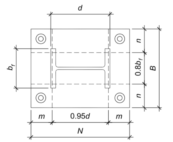
$N=$ base plate length, $mm$
$W=$base plate width, $mm$
$b_f=$column flange width, $mm$
$d=$ overall column depth, $mm$
$n'=$ yield-line theory cantilever distance from column web or column flange, $mm$
$F_{EXX}=$ filler metal classification strength, $\frac{N}{mm^2}$
Input data
To kick-off our calculation, we collect some input data what we will need later in the formulas. I list them here in one place, so it can help you later build up your own workflow in Excel, Matlab, Mathcad or maybe a Python script. Later, during the analysis we will use all these inputs and in this post, I will use real figures from a 40m, lattice, 3-legged tower with angular members.
$P_u = 1540kN$
$P_t = 1485kN$
$f_{c'} = 25 \frac{N}{mm^2}$
$f_y = 345 \frac{N}{mm^2}$
$f_{yre} = 420 \frac{N}{mm^2}$
$F_{EXX}=345 \frac{N}{mm^2}$
$\phi = 0.65$
$b_f=160mm$, width of flange
$d = 160mm$, depth of flange
$W_{prov}=450mm$, provided base plate width
$t_{prov}=50mm$, base plate thickness provided
$a_w=8mm$, Minimum size of fillet welds according to AISC specification Table J2.4
$c_{a,min}=215mm$
$s_{max}=141mm$
$c_{a,max}=285mm$
$A_{NC}=0.49m^2$, concrete brakeout cone area for group
$n_{re}=28$, number of vertical reinforcement bars
$d_{re1}=20mm$, diameter of vertical reinforcement bars
Minimum base-plate area
The minimum base plate area can be determined by the following equation:
$$ A_{1(req)}=\frac{P_u}{\phi \cdot 0.85 \cdot f_{c'}} $$
thus,
$$ A_{1(req)}=\frac{1540kN}{0.85 \cdot 0.85 \cdot 25\frac{N}{mm^2}} = 111493mm^2 $$
To optimize the base plate dimensions, N and B:
$$ N \approx \sqrt{ A_{1,(req)}} + \Delta $$
where,
$$ \Delta = \frac{0.95d-0.8b_f}{2} $$
then,
$$ B = \frac{A_{1,(req)}}{N} $$
so,if $d=b_f$, then
$$ \Delta = N \cdot \frac{(0.95d-0.8b_f)}{2} = 12mm $$
and the required width,
$$ W_{req} = \sqrt{ A_{1,(req)}} + \Delta = 346mm $$
Since all the tower legs are equal angles the length shall be equal to width.
$$ N_{req} = W_{req} $$
My base plate looks like as below, so I can check now if the provided width is sufficient or not.
$$ W_{prov} = 450 mm > W_{req} = 346mm \quad \pmb{\color{green} \surd}$$
In my case the $A_1$ and $A_2$ are identical as the tower main leg is an equal angle.
Calculate the required base plate thickness
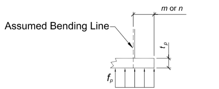
For axially loaded base plates, the bearing stress under the base plate is assumed uniformly distributed and can be expressed as
$$ f_{pu} = \frac{P_u}{B \cdot N} $$
This bearing pressure causes bending in the base plate at the assumed critical sections shown in the figure below:
The required strength of the base plate can be determined
as
$$ M_{pl} = f_{pu} \left( \frac{l^2}{2} \right) $$
Where the critical base plate cantilever dimension, $l$, is the larger of $m$, $n$, and $λn′$.
$$ m = \frac{N-0.95d}{2} $$
$$ n = \frac{B-0.8b_f}{2} $$
$$ \lambda n' = \lambda \sqrt{ \frac{db_f}{4} } $$
where,
$$ \lambda = \frac{2 \sqrt{X}}{1+\sqrt{1-X}} \leq 1 $$
and where,
$$ X = \left( \frac{4db_f}{(d+b_f)^2} \right)\frac{P_u}{\phi_c P_p} = 0.55$$
then,
$$ \lambda = \frac{2 \sqrt{0.551}}{1+\sqrt{1-0.551}} = 0.89 \leq 1 \quad \pmb{\color{green} \surd} $$
Then we can calculate $\lambda n'$
$$ \lambda n' = 0.89 \sqrt{ \frac{db_f}{4} } = 35.5mm $$
Then looking for the maximum of $l$ turns out to be:
$$ l_{max} = 157mm $$
It is worth mentioning that it is conservative to use $\lambda = 1.0$. For the yielding limit state, the required minimum thickness of the base plate can be calculated as follows (Thornton,1990) (AISC, 2005):
$$ t_{min} = l \sqrt{ \frac{2P_u}{\phi F_y N_{prov}W_{prov}} } = 40.9mm$$
Since
$$t_{prov} = 50mm \geq t_{min} = 40.9mm \quad \pmb{\color{green} \surd}$$
Anchor check
We will have couple of checks for the anchors as well, so let's see them each by each.
Welding
Check the welding of the column to the base plate. Since there are anchor bolts outside the flanges of the angle, the forces can be assumed to be distributed onto the both full legs of the angle. Conservatively the thickness and radius of the angle will not be applied. Fillet weld will be applied to both sides of the main leg + to the stiffeners as lengthen the legs of the angle and 2 perpendicular short stiffeners (see drawing above) as min. 100mm in length. Maximum welding load then:
$$ b_{eff} = b_f \cdot 2 + 2 \cdot (b_f - 16mm - 6mm) $$
$$ + 100mm \cdot 2 \cdot 2 + 100mm \cdot 2 \cdot 2 = 1396mm $$
Max load:
$$ f_{max} = \frac{P_t}{b_{eff}} = 1064 \frac{N}{mm} $$
Minimum size of fillet welds according to AISC specification Table J2.4:
$$ a_w = 8mm $$
Nominal weld strength per mm for the fillet weld:
$$ R_n = f_{nw} a_w = 2148 \frac{N}{mm} $$
where,
$$ f_{nw} = 0.6 \cdot F_{EXX} \cdot \left[ 1.0 + 0.5 \cdot \left( \sin \frac{\pi}{4} \right)^{1.5} \right] = 269 \frac{N}{mm^2} $$
so,
$$ \frac{f_{max}}{R_n} = 0.50 \leq 1.0 \quad \pmb{\color{green} \surd} $$
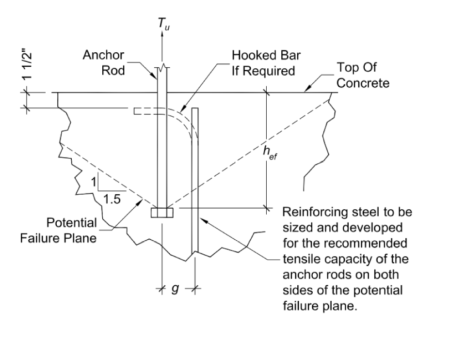
Brakeout strength
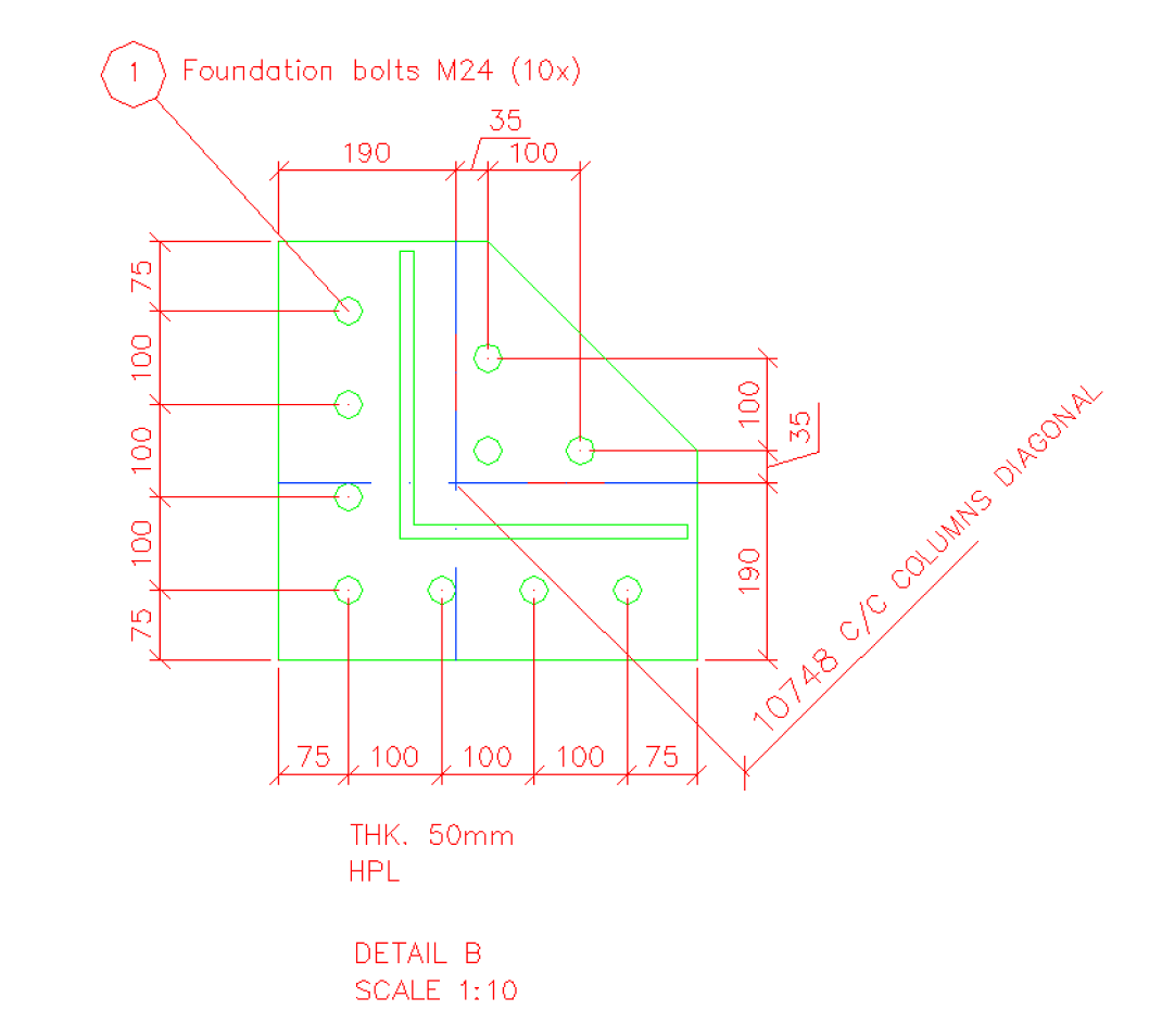
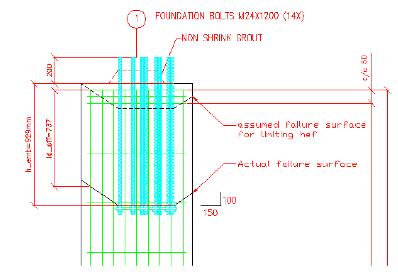
The anchors installed in the column, thus the brake out strength is limited by the column cross section. See image below. The anchor load is transferred to the vertical reinforcing steel in the column. The required area of steel has been designed as part of the foundation design.
The column is arranged as follows:
Concrete brakeout strength of anchors in tension, ACI318-05M Appendix D The basic brakeout strength:
$$ N_b = k_c \sqrt{f_{c'}} \cdot h_{ef}^{1.5} = 130.9kN$$
where;
$ k_c = 10 $, for cast-in anchors
The eccentricity factor:
$$ \psi_{ecN} = 1.0 $$
Modification factors for edge effects in tension
$$ c_{a,min} = 215mm $$
Since the anchors are located less than $1.5 h_{ef}$, from three or more edges, the value of $h_{ef}$ as per below
$$s_{max}=141mm$$
$$c_{a,max} = 285mm$$
then,
$$h_{ef} = max \left( \frac{c_{a,max}}{1.5}, c_{a,min} \cdot \frac{1}{3} \right) = 190mm$$
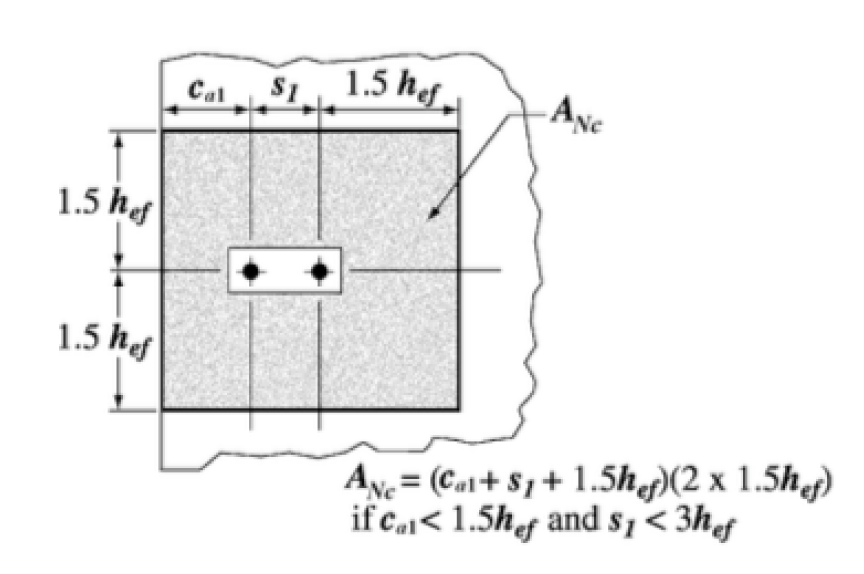
The concrete brakeout cone area for group:
$$ A_{Nc} = 750^2 = 562500mm^2$$
Concrete brakeout cone area for a single anchor:
$$ A_{Nco} = 9 \cdot h_{ef}^2 = 324900mm^2$$
The modification factor for edge effects for single anchors or anchor groups loaded in tension is:
if $c_{a,min} \geq 1.5h_{ef}$
$$ \psi_{ed,N} = 1.0$$
or, if $c_{a,min} < 1.5h_{ef} $
$$ \psi_{ed,N} = 0.7+0.3 \frac{c_{a,min}}{1.5h_{ef}}$$
We have the second case here, so
$$ \psi_{ed,N} = 0.7+0.3 \frac{215mm}{1.5 \cdot 190mm} = 0.926$$
Cracking factor, assumed that the region of analysis where the anchors are placed is cracked.
$$ \psi_{cN} = 1.0 $$
So, the breakout strength can be computed as follow and the tension shall not exceed:
$$ N_{cbg} = \frac{A_{Nc}}{A_{Nco}} \cdot \psi_{ec,N} \cdot \psi_{ed,N} \cdot \psi_{c,N} \cdot \psi_{cp,N} \cdot N_b$$
from here,
$$ \phi \cdot N_{cbg} = 136.5kN \ngeq 1485kN \quad \pmb{\color{red} {fail} } $$
The breakout strength is not satisfactory, thus it is necessary to transfer the load from the anchors to the vertical reinforcing steel in the column. Required area of steel:
$$ A_{req} = \frac{P_t}{0.9 f_{yre}} = 3929mm^2$$
For deformed bars, according to ACI318-05M 12.2.3 below the necessary development length for the rebars without hooks. Necessary vertical length
$l_d$ computed as below:
$$ l_d = \frac{f_{yre}}{1.1 \sqrt{f_{c'}}} \frac{\psi_t \psi_e \psi_s \lambda}{ \left( \frac{c_b+K_{tr}}{d_b} \right)}$$
where,
$$ K_{tr} = \frac{A_{tr} \cdot f_{yre}}{10 \cdot s \cdot n} $$
where,
$n=9$, is the number of bars or wires being spliced or developed along the plane of splitting
$s=88mm$, is the center-to-center spacing of items, in this case the longitudinal reinforcement
$A_{tr} $, is the total cross sectional area of all transverse reinforcement within spacing $s$ that crosses the potential plane of splitting through the reinforcement being developed ,$mm^2$
So,
$$ K_{tr} = 20.8 \frac{N}{mm} $$
$$ \frac{c_b+K_{tr}}{d_b} > 2.5 $$
The provision of 12.2.2 and 12.2.3 give a two-tier approach. The user of the standard (ACI318) can either calculate $l_d$ based on the actual $\frac{c_b+K_{tr}}{d_b}$ (12.2.3) or calculate $l_d$ using 12.2.2, which is based on two preselected values of $\frac{c_b+K_{tr}}{d_b}$. In my case I use the first approach.
$ \psi_e = 1.0 $
$ \psi_t = 1.0 $
$ \psi_s = 1.0 $
$ \lambda = 1.0 $
Please note that by the rules of 12.2.4 these factors can be different in other cases, where epoxy coating is present on the rebars, or light weight concrete is used, or just even smaller bars than 19mm in diameter. By applying all these $l_d$ yields to be:
$$ l_d = 611mm $$
The column reinforcement are located at the edge of the column (see drawing above). Using a Class B splice factor with 1.3 the necessary minimum development length $l_e$ as below:
$$ l_e= \frac{ P_t \cdot 1.3 \cdot l_d}{ n_{re} \cdot d_{re1}^2 \cdot \frac{\pi}{4} \cdot 0.9 \cdot f_{yre} } = 355mm $$
Now we can check if the provided development legnth are sufficient:
$$ l_{d,eff} = (1200 - 200 - 50 - 65)mm - \frac{c_{a,max} - 50mm}{1.5} = 728mm $$
so,
$$ l_{d,eff} = 728mm > l_e = 355mm \quad \pmb{\color{green} \surd} $$
The necessary development length, $l_e$ is provided.
You can see that a fair amount of steps need to be done for a proper base plate and anchor checks. I hope you liked this guide and it can help you in your job. If so, please drop a comment below or post a question.


